| Building
Tamiya's M3 Lee |
 |
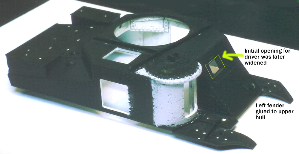
The Upper Hull ExteriorThe VP set requires some surgery to the Lee hull. I removed the fake wall sections from the front sponson gun opening, the wall above the engine deck, and the molded engine screen. To cut out the large circle needed for the turret basket, I first glued a sheet of scrap plastic to cover the bottom of the opening that accommodates the kit's turret. That allowed me to find the center point and used a scribe to mark my circumference. Rather than trying to saw out a perfect circle, I just used my Xuron nippers to nibble away at the plastic until I hit my mark, followed with some filing, sanding, and plenty of dry fitting.
The kit does not have an opening for the driver's visor, so that needs to be cut out as well. I sized it according to a resin front driver's visor I purchased from Paul Roberts to replace the undersized kit part; Tamiya's visor and surrounding bullet splash is as wide as just the visor in its correctly scaled counterpart. Since I wanted to have the visor opened, I removed the splash from the resin piece. The separation between the splash and visor in the Tamiya piece was filled and sanded, giving me the correct width of the visor to fit into the pocket of the resin splash. Again, the reason for using the styrene visor was to get a better bond to the plastic hull and lessen any chance of breakage. The visor, which was tricked out with photoetch and a casting number, was the last item glued into place after painting and weathering. The Tamiya instructions have you attach the front left fender (#A8) to the left front edge of the lower hull, but I glued it directly to the bottom edge of the upper hull after trimming off the back corner as specified by the Verlinden instructions. That way, if there were any gaps when mating the top and bottom hull sections together, they would appear on the underside of the fenders (the right fender is molded onto the hull) and less conspicuous if filled in. All of the locating holes for various pieces were filled with Testors' Contour Putty.
I used a lot of casting numbers on the tank, pulled from Academy's tank destroyer sets. The appear in two places on the transmission casing, on the cupola (purposely upside down, as seen on a real cupola), atop the 75mm housing, and on this inside surface of the driver's visor. Both gun barrels were replaced and some Eduard p/e was applied around hull in the later stages of construction. Tools were repositioned according to the Squadron Signal drawings; it appears that Tamiya's is a very early layout. The headlights were ground out and replaced with MV 116 lenses. Wiring was run from the lights to their entry points in the hull in both the front and back of the tank. I had
a spare folded .30 tripod that I wrapped in some tissue paper and
tied it off, and added a couple pieces of thin metal to serve as
the hangers that appear on the front left wall of the hull above
the fender. Based on an Allied and Axis photo, I added a
retaining bar across the back of the engine deck, undoubtedly used
by this crew to keep gear from sliding off the back and providing
attachment points to secure their stowage. Another crew had welded
some braces to the rear fender to hold a box of rations in place,
which I copied. Introduction
and Research Notes |
 |
 |
 |
 |
 |
 |
 |
 |
 |
 |
 |
 |
|