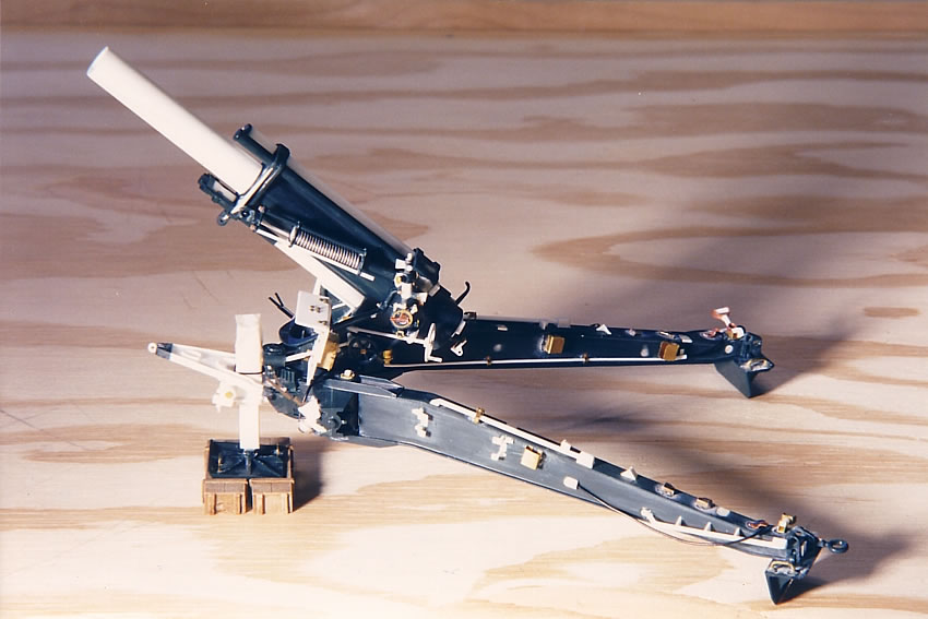
Building the Carriage Assembly
 The
carriage also offers numerous areas for improvement. Since I did
not need to have the gun swivel, I was able to glue the cradle and
trails in place. This made the other detailing a bit easier since
I didn't have any rascally moving parts. The
carriage also offers numerous areas for improvement. Since I did
not need to have the gun swivel, I was able to glue the cradle and
trails in place. This made the other detailing a bit easier since
I didn't have any rascally moving parts.
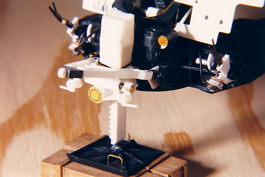
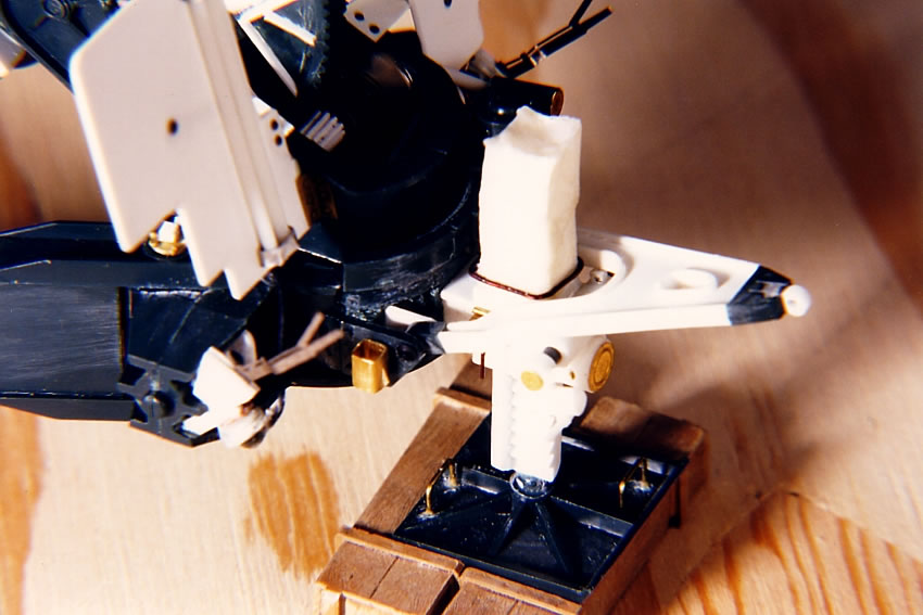
- While
part 24 is bogus and only used to keep the gun elevation in place
when playing with the model, I glued it in anyway to allow me
to adjust the elevation for the purpose of the diorama, at which
time I did glue the gun in the trunnion (or cradle, as it's called
in the directions).
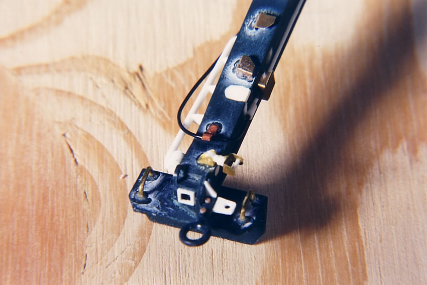
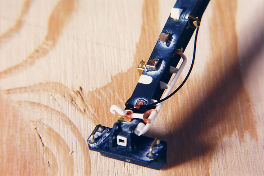
- Parts
33 and 34 are what I refer to in Item 6 on the howitzer construction
page, where the equilibrator attaches to the trunnion. I cut off
the pivot rods from these pieces and fashioned bits of Plastruct
to match the shape of the plates that were present. The equilibrator
end would be sandwiched between these two plates during the final
step of assembly.
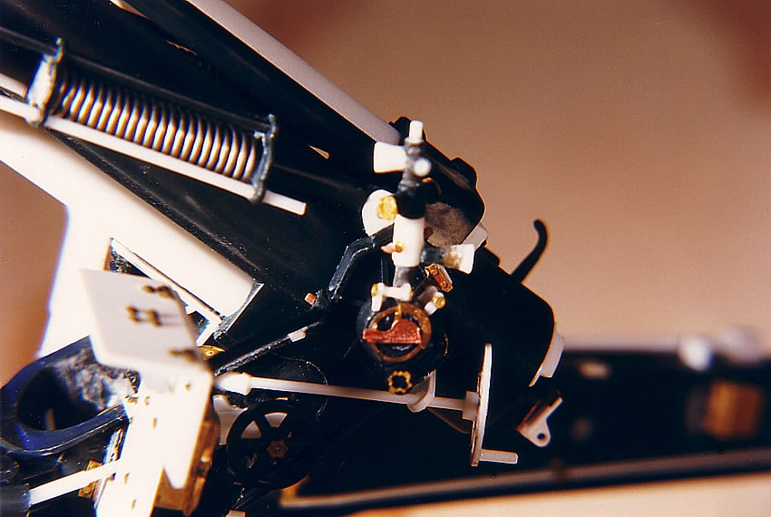
- Because
it is an obvious detail when looking at the front of the gun,
I added a homemade elevating pinion to connect with the kit's
elevating arc between the trunnion arms; other bits were added
for housings that encased the elevating worm and elevating worm
wheel.
- The
traverse gearbox and shaft (part 31) needs to be mounted higher.
A junction was made for the traversing handwheel.

- Likewise
the work is necessary on the elevating handwheel shaft, which
passes through the trunnion to the elevating worm on the other
side. The shaft needs to for the elevating handwheel extends past
the farthest edge of the trunnion. The kit's handwheel is much
smaller than the real thing. I was leery of trying to scratchbuild
one myself, but I managed to successfully accomplish it the first
time out.
- The
telescope is extremely simplified. I basically deconstructed the
kit's parts and rebuilt them with added bits of brass and plastic.
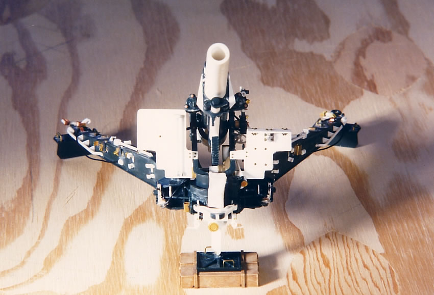
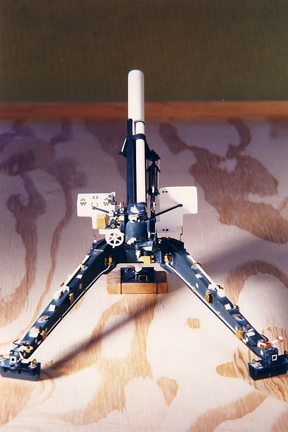
- The
shields need to be thinned and reshaped. I used them as patterns
for new shields on thinner plastic card. I then recut them to
approximate the correct shapes. The shield on the gunner's side
does fold down, and is often seen folded while in use, so I constructed
mine that way. The shield on the other side is one piece, not
two as the kit portrays. On the outside of this shield are stowed
two rods used as ratchet handles for the firing jack when emplacing
the gun. Contrary to the kit, there is only one storage box, located
on the gunner's side for the gun sight. I used a little brass
box found in the model railroad section. Rivets were added where
necessary. The connecting points of the braces (parts 46) were
thinned and modified, and connected farther up the trunnion than
directed by the kit's instructions (the empty receiving points
in the trunnion were patched with plastic card). Missing triangular
shield braces were made from plastic card and detailed with rivets.
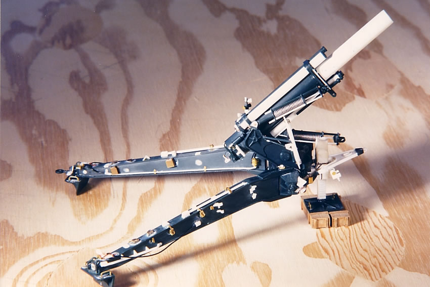
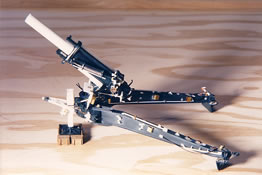
- I
carved off all detail on the sides and tops of the trails and
patched the holes. New stowage clips and holders for the handspikes,
ammo tray, jack float, rammer and aiming posts were made from
plastic and brass (it pays to hang on to any leftover photo etch
parts from your tanks!). Kurt thoughtfully provided measurements
of the placement of these items in his photos. These items were
welded onto the trails and I tried to indicate that with beads
of thick superglue. Grab handles were added to the outsides of
the trails, as were brackets to hold the spades in place while
the howitzer is traveled. A trail lock assembly was also scratchbuilt.
- The
kit errs in having brake fluid cylinders molded onto both the
trails and the interior face of the carriage. I ground off both
the incorrect cylinders on the carriage and the ones on the trails,
and correctly placed new ones (again brass pieces from the railroad
department) on the trails. I ran new conduit for the brake lines
along the inside faces of the trails. When the air brake lines
were disconnected from the towing vehicle, they were locked into
dummy couplings on the outer sides of the trails.
- The
ends of the trails need considerable attention. Rather than being
a solid hump over the top end, there are actually two protrusions
on either edge, with a channel running between them. I was able
to replicate this by drilling a hole through the center of the
hump, from one side to the other. I then filed down the center,
which gave me the end pieces and the channel produced by the drill.
The tow ring is secured to the left trail (as looking at the back
of the gun). I cemented the spades in place and added lifting
handles.
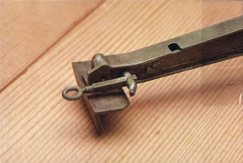
- The
plates (parts 50) to hold the trails to the carriage differ from
those in the museum photos, but I was not inclined to change them.
I glued the trails in place to the carriage, and then capped off
the plates with some brass coverings from the railroad department.
- Air
brake levers came from the Eduard 105 howitzer photo etch. The
brake diaphragms are more bits from the railroad department. The
latch plate and slack adjuster were handmade.
- The
firing jack was used to raise the carriage so the wheels were
off the ground and the gun's recoil didn't send the piece rolling
backwards. The kit's jack, again modified so it can be played
with, is the M1A2 postwar version. The tech manual and Mike Powell's
photos gave me enough info to scratchbuild the correct jack and
a new traveling lock. A canvas cover secured to the top of the
jack to keep it clean was made of tissue soaked in glue and secured
with wire. Another cover for the bottom of the jack was also scratchbuilt
and chained to the traveling lock. The kit's float that the jack
sat on was given a couple wire handles. Various pins and chains
were added where appropriate (chains were added after the kit
was primed to reduce help maintain the detail). The jack's ratchet
handles were stowed on the gun's front shield.
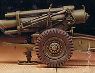
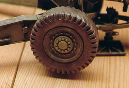
-
The most commonly seen wheels during the war were the diamond
pattern and the zigzag pattern treads. I first smoothed the road-contact
surfaces of the tires with an X-Acto knife and sandpaper. I tried
carving the diamonds with a Dremel but wasn't able to get the
angles without cutting into the grooved pattern around the edge
of the tire, which I wanted to preserve. I then attempted to replicate
the zigzag pattern around the circumference of the tire as a straight
line (the zigzag itself being impossible to reproduce), again
using an X-Acto. But again the results were unsatisfactory.
Several
modelers on Track-Link suggested using the rubber tires from
Tamiya's Dragon Wagon, which can be purchased separately. These
tires, while still not the correct pattern, are at least World
War II vintage, and the size is right on. One could argue that
they would be adequate replacements on the front line if the
right tires were not at the supply depot.
Using
these tires necessitated sanding down the Italeri wheel (#54)
between 1/8 and 3/16 inches. I test fitted the tires onto the
wheels several times, including the wheel rims (#57) on the
back sides, to make sure I didn't snd off too much. When the
tires were snug and no gaps present, I glued the rims to the
wheels, and the tires slipped over nicely. I spray painted the
wheel assembly before affixing the tires with some white glue.
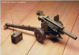
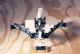
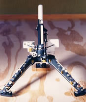
As
you can see from my photos there are enough doodads added to make
handling the carriage an exercise in extreme caution.
Introduction
Background
on the 155mm Howitzer
Overview
of the Model and References
Building
the Howitzer Assembly
Building the
Carriage Assembly
Painting and
Accessories
Pictures
from the Technical Manual
155mm
Ammunition
Pictures
of Museum 155mm Howitzer
Diorama:
"Mail Call for the Sons of Thor"
|