Building
the Howitzer Assembly
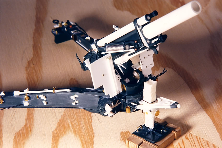
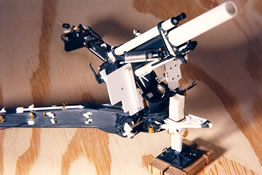
The
model essentially breaks down to two assemblies: the howitzer and
the carriage, including the cradle and trails. The Italeri/Testors
pictures are of a finished model; click on my in-progress photos
with the border to open a larger picture in a new window.
- The
kit's two-part barrel - more correctly called the tube - was replaced
with a 3/8" Butyrate tube from Plastruct, since the final
result of gluing the kit's pieces was that they were more oval
than round. The replacement tube had to be sanded down some in
order to fit within the barrel sleeve. I also replaced the recuperator
and recoil cylinders (parts 14 and 17) with 11/16" and 5/32"
Evergreen tubes. The closed tip of the kit's recuperator cylinder
was sawed off, adjusted and glued onto the open end of the Plastruct
tube.
 |
 |
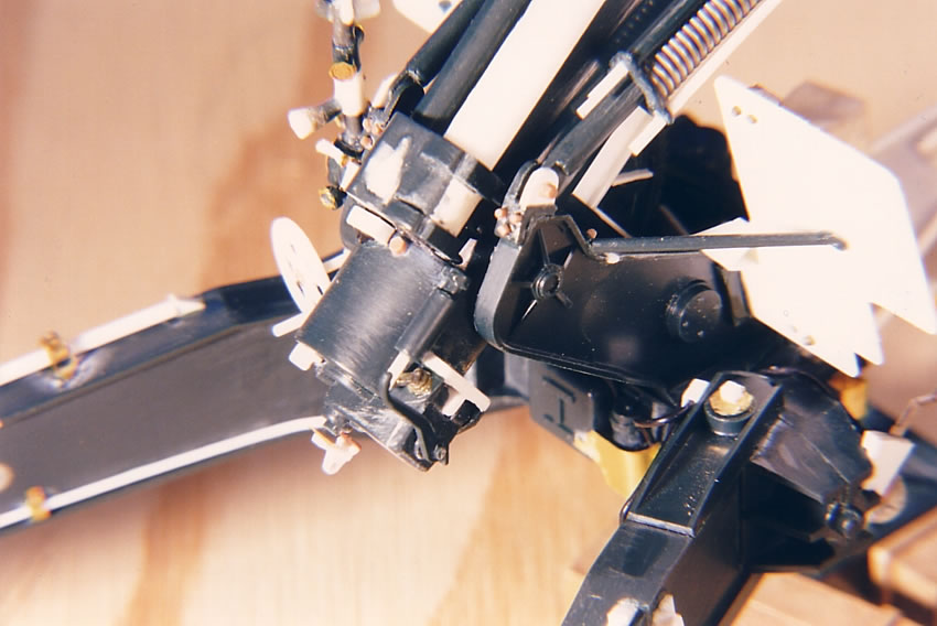
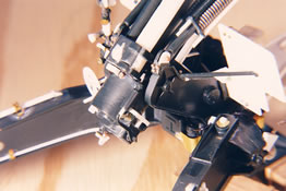 The
breech was extensively reworked. It's designed to swing open or
closed, but I glued it closed (the breech block itself is significantly
undersized and would need to be reworked if left open). The breech
has a rounded extension on the right topside, featuring a circle
with a bar through it, which I removed. (The circle and bar is
actually on the back side of part 5 and I used a piece from the
Eduard photo etch for the M1 105 Howitzer to place this detail
on the reworked part 5.) A new squarish extension was added on
the left top of the barrel, to which the counter recoil cylinder
was attached on the real gun. The counter balance (part 66) can
be used, but needs to be turned around so the end that glues to
the breech is actually at the front (barrel side) of the piece.
I used some bits of plastic and Grandt Line bolts to create the
armature that connects to the top of the breechblock's hinge on
the side of the breech. A percussion hammer was added from brass
pieces. A lanyard was connected to this after the gun was loaded
and ready to fire. The
breech was extensively reworked. It's designed to swing open or
closed, but I glued it closed (the breech block itself is significantly
undersized and would need to be reworked if left open). The breech
has a rounded extension on the right topside, featuring a circle
with a bar through it, which I removed. (The circle and bar is
actually on the back side of part 5 and I used a piece from the
Eduard photo etch for the M1 105 Howitzer to place this detail
on the reworked part 5.) A new squarish extension was added on
the left top of the barrel, to which the counter recoil cylinder
was attached on the real gun. The counter balance (part 66) can
be used, but needs to be turned around so the end that glues to
the breech is actually at the front (barrel side) of the piece.
I used some bits of plastic and Grandt Line bolts to create the
armature that connects to the top of the breechblock's hinge on
the side of the breech. A percussion hammer was added from brass
pieces. A lanyard was connected to this after the gun was loaded
and ready to fire.
- The
kit's recuperator yoke (aka "cylinder yoke") is simplified,
likely due to molding purposes. I added some strips of plastic
card to replace the missing front flange. The bottom of the yoke
has a pin for the traveling lock, but this really should be cut
off and a hole made through this tab. The tab's corners should
be cropped, and a supporting flange added.
- Part
5 receives the back ends of the recuperator and counter recoil
cylinders (kit parts 14 and 18). Its shape is significantly simplified,
and I was able to create a more credible appearance using a small
file and some putty.
-
The elevator gear (part 4) had a strip of Plastruct added across
the narrow top edge, and three strengthen strips added to the
sides.
 |
 |
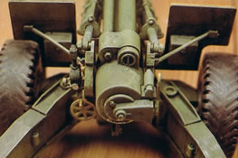
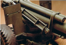
- The
pair of two-piece equilibrator springs was assembled, and when
dry they were carefully cut apart to remove the solid spring areas
and the adjoining flat plastic on the other side of the piece.
This left one remaining rod on each equilibrator piece. I glued
in springs made from thin solder wire, then pieces of Plastruct
rod to replace the missing parts. These rods were bolted at the
barrel end of the springs, and extended through the plate and
secured with nuts on the breech end of the springs. The middle
plate between the two ends has a hole in it in order to allow
the model's gun to be raised (the rods slide through these holes,
whereas on a real gun they would push against the sliding center
plate as the springs expanded). The hole was filled with putty.
While the kit is correct that the ends at the forward end of the
barrel were bolted to the sides of the cylinder yoke, the ends
that attach to the trunnion on the carriage are not bolted, as
the kit builds up. Rather, there were companion plates on the
outsides of the trunnion, and the equilibrator was secured between
those two plates. To accomplish this, you need to trim down the
attachment points on this end of the springs. (I did not glue
the springs, nor the howitzer assembly, in place for these photos,
as I planned to paint them separately from the carriage.)
-
Because I try to minimize breaking things during assembly, I often
leave small fragile parts off until the last possible moment.
I fashioned the percussion hammer and glued the breechblock lever
(part 67) just before painting.
Introduction
Background
on the 155mm Howitzer
Overview
of the Model and References
Building
the Howitzer Assembly
Building the
Carriage Assembly
Painting and
Accessories
Pictures
from the Technical Manual
155mm
Ammunition
Pictures
of Museum 155mm Howitzer
Diorama:
"Mail Call for the Sons of Thor"
|