|
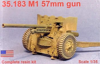
M1
57mm
Gun |
 |
|
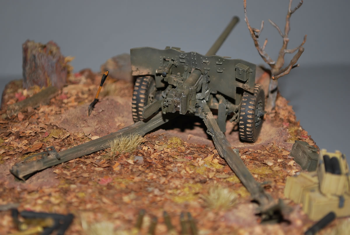
The 57mm gun M1 was the U.S. military's adaptation of the British 6-pounder Mark II gun. As the American government had agreed to build the weapon for Great Britain as part of the Lend-Lease program, it was accepted into the ordnance catalogue with one performance variation of any significant: the barrel was lengthened 16 inches to produce a greater muzzle velocity (100 feet per second). For both the U.S. and British versions, the gun was mounted on a carriage designed by the Hotchkiss Company of France before the turn of the century. The U.S. made changes to the towing mechanisms and shortened the long wing-shaped shield. The gun first saw action in North Africa in 1942, and was used almost exclusively in the Mediterranean and European fighting. Production was halted in early 1944 after some 16,000 guns were built. It was served by a crew of ten and, according to the Field Manual 23-75 of June, 1944,towed by the 1.5 ton 6x6 truck but there is photographic evidence that it was occasionally moved by halftrack as well. It fired both armored-piercing and high-explosive shells, and had a nasty recoil that crews did not like. Modelers are probably familiar with the two 1970s iterations of the 6-pounder have been produced: the inferior Tamiya gun, and a mold that has bounced from Peerless Max to Italeri and then reboxed by Testor and Zvezda. Between the two, the Italeri kit is the better choice for conversion to the U.S. standard, and it's not overly difficult for a modeler with some skill. But in 2006, Resicast produced a highly accurate resin kit of the American gun that far eclipses its plastic cousin. Unfortunately, the muddled instructions do not match the fine quality of the model. The Instructions I saluted Resicast for it's fine instructions included with their field kitchen set. But this model is much more complicated and a number of the grainy black and white photos of the building process that are supposed to guide the way are excessively washed out and indistinct, making placement of parts challenging. Though there are a few technical manual photos at the back of the instruction pamphlet and I was armed with Easy 1 Productions' CD-ROM, Light Artillery and Anti-Tank Guns, I decided to have a trial run and built up the Italeri/Zvezda kit I'd had on the shelf for years. While the differences between the kits are quite distinct, there is enough commonality between the British and American guns that I felt a bit more confident taking on the Resicast set. However, the built-up Italeri/Zvezda was quite helpful walking me through some significant holes in Resicast's instructions, which are nearly the downfall of an otherwise excellent kit. This definitely is a project for modelers with some experience in resin and a very light touch, since there are many small, fragile parts. Tweezers and a new blade in the hobby knife are essential. One thing I do like about Resicast's instructions is that the parts and their corresponding ID numbers are listed, which is not only helpful in building the kit, it also helps me understand the item better. Resicast notes when spare pieces are included. These spares are handy since many are delicate and vulnerable to breakage or molding errors. The fret of brass photoetched parts is also identified: you get a few brackets for the gun's trails, a range finder for the sight, and a set of stamped bases for the resin 57mm rounds (as well as some unused bases and parts for Resicast's 6-pounder kit). The first image of the construction photos shows the forward connecting ends of the trails, which are interwoven with a mounting bracket to the axle and secured in place by the frame (#1)—and a saddle pivot nut (#0) that serves as a spacer but wasn't necessary in my build. Anyway, that is the sole introduction to these parts, with the note that you should use a pointed file to open the holes in these pieces to their proper diameter, which is the vertical axle under the frame. This happens to be the same size as a round toothpick. Building the Gun
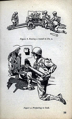
What is supposed to be the breech lever is misidentified as part 40, the trip lever, which of course looks something like a lever. What I didn't realize until later was that there was another casting in the bag that had the actual breech lever on it, but it is stamped part 35. So review your parts carefully. A nice touch here is that you have the option of building the breech closed or open. Going a little farther, I came to a photo that shows adding part 40 to the left side of the breech—opposite of the part 40 I installed a few steps before. Part of my puzzlement was due to Resicast's inclusion of the ID numbers for previously placed parts in succeeding instructions. This is good for seeing what the parts look like at different angles (sometimes necessary for accurately placing the parts). But it can also lead you to believe you are adding those parts now if you've taken a break and didn't commit the building sequence to memory. And then you get to a photo the again misidentifies these same parts 40 and 41 as one another, again the trip lever and the actuating lever. Another item to watch is part 29, called the recoil part. It looks like a hexagonal nut on a disc. Its shown being attached to either the bottom of the breech block or the sleigh. Several images later it is more clearly shown attached to the end of the sleigh. Building the sight mechanism went together easily enough, but the parts are very small and thin, including three wing nuts and the range finder. The instructions show the range finder installed with the longer side of the rectangle down, but the technical manual shows it placed vertically, which is what I did. I set this aside and added it to the gun only after everything else was built.
After instructing you to add the sight to the frame, the instructions jump to fitting out the details on the trails. In the photos the trails are already attached to the axle, which has the gun frame in place, but there are no instructions on how this was all assembled. This is where the Zvezda kit came in handy. I left it off while I cleaned out the connecting points of the trail and adjacent parts and worked on their attachment to the axle. Again, to minimize damage to the gun assembly I left it off until after all the trail parts were installed. I know that I want to use this kit in a deployed setting, so I built the gun with the trails splayed and the firing supports down for action. (Position the firing supports at 3:00 for travel, or at 6:00 for when the gun is in action; ideally, the crew will have dug the ground out below the tires so the weapon rests on the firing supports.) However, it appears there should be a second half to the retaining collars that hold the firing supports to the axle. I found a stray part "G" in one of the baggies that resembled a collar, but there was only one and not two, and there was no reference for it in the instructions list or in the photos. Another odd omission from the kit are two handjacks that would be used to help emplace the gun. I made a pair from plastic rod the approximate diameter of the hole in the stowage bracket and the length of the distance between the bracket and the plate (which I had to add) where the handjack rested. I suspect there may have been a strap to secure the jacks but haven't seen them in photos.
While the instructions show that you can swivel the drawbar assembly (with the lunette that attaches to the towing vehicle), it would be helpful to tell the modeler that the "up" position was for manhandling the gun into place, and the down position was for towing. Final Assembly I left the tires off the model so the gun and carriage can be painted and weathered separately. The gun was fielded with both commercial and combat styles of tires. The lower shield is connected to the axle with a couple paper thin fin brackets. Be careful so you glue them properly to the shield. There is no direction for attaching the shield (43) to the cradle, but it should be pretty evident. The gun barrel is shown attached here as well; it's a snug fit. I added it after the shield so as not to have any problem slipping the shield over the flared end of the barrel. The apron is shown attached in the raised position, secured with a pair of photoetched hooks passed through rings. This is a little tricky but can be done. Or you can leave the apron down if the gun is in firing position. The kit comes with some tools, but they aren't shown in the instructions. In an impressive bit of casting, the apron has several tie-downs that are hollow or nearly hollow and you could work some paper straps through them if you wanted to secure the tools for travel. But I bet the crews just tossed them into the back of their prime mover.
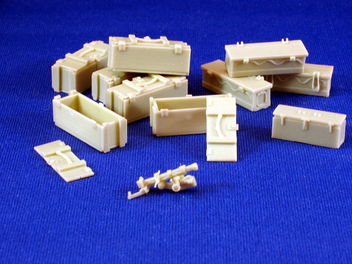
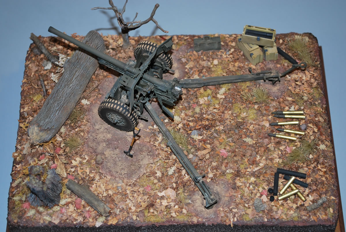
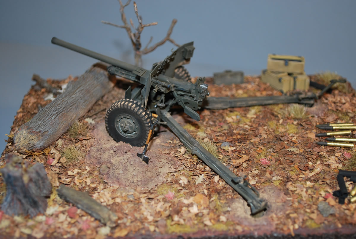
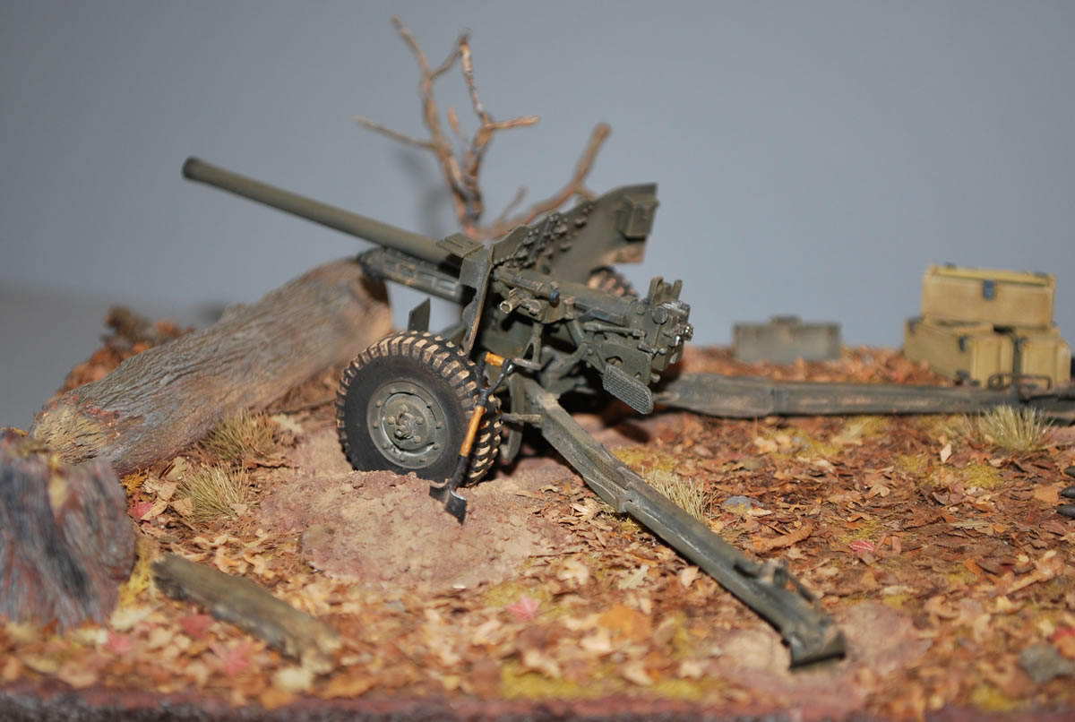
All of the confusion and frustration caused by the directions is offset to a good extent by Resicast's inclusion of a good assortment of ordnance, including armor-piercing and high-explosive shells and empty casings (three each). Four closed tubes are complemented by four open tubes with detached tops. Four closed and two open wooden boxes are joined by two steel boxes and one M6 chest. This is the right way to treat the modeler. Coming close to such completeness, a set of decal markings for the ammo containers would be the crowning touch, but we'll have to research and create the markings on our own. Quality of sculpting and molding is excellent. The detail is crisp and complete save for a few absent bolts on the carriage and the aforementioned missing parts. Beyond the challenging instructions, the kit goes together well. There is an understandable presence of thin flash around a number of the delicate pieces that needs care when cleaning. There was just one air bubble embedded in the shield but it caused no problem. This kit far surpasses the Italeri offering and certainly presents the M1 as fielded by the U.S. It is not inexpensive, however, and Resicast needs to improve the proofreading and overall quality of its instructions to help ensure the modeler will have a more enjoyable experience with this complicated kit. This product sample was provided by Resicast. Mark Corbett displayed this excellent vignette featuring the Resicast 57mm at the 2008 AMPS show.
-tss-
|
 Resicast
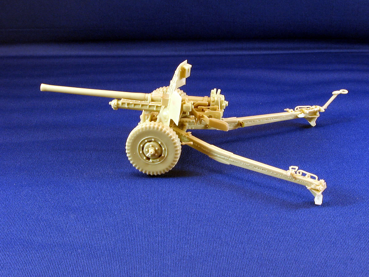
 Building
the Trails
Building
the Trails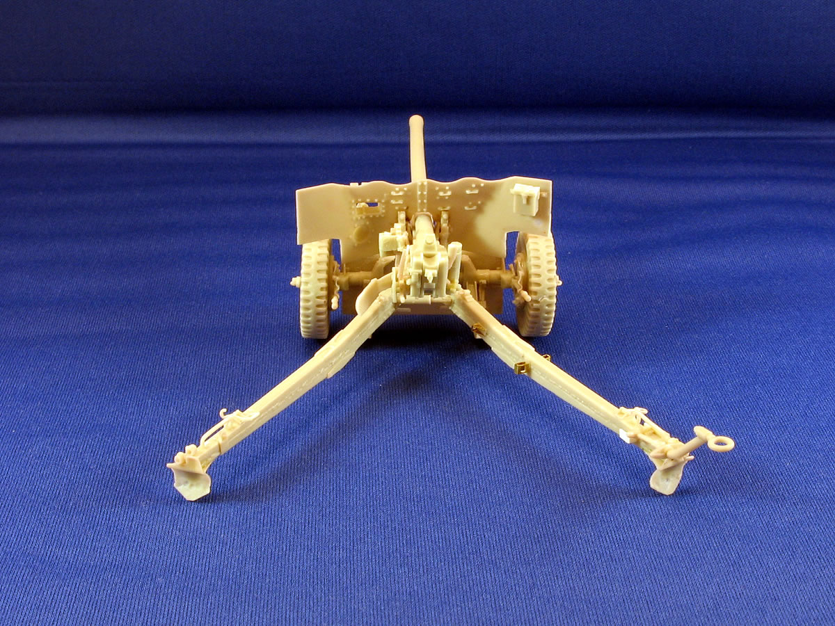
 |
 |
 |
 |
 |
 |
 |
 |
 |
 |
 |
 |
|