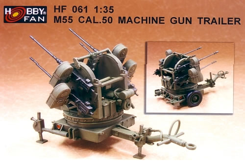
| M55
Cal. 50 Machine Gun Trailer |
 |
Hobby
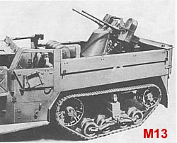
Fan This is, for the most part, a well executed styrene and resin model of the rarely seen towed version of the quad .50 Maxon mount that armed the M16 halftrack. The gun assembly in this kit, molded in styrene, had its origins in AFV Club's Vietnam era M35A1 Guntruck. At the end of this construction article, I've listed some web references. Roy Chow also provided me with images from the technical manual. There are some differences between all these references—and the kit as well—that I didn't take additional time to track down and reconcile. This is a kit that improves with a little bit of TLC, particularly with regard to the power plant in the rear end. Background After Army experiments with aircraft mounts for a twin .50 machine gun antiaircraft weapon proved successful, the W.L. Maxon Company was contracted to develop and produce a vehicle-mounted version. This resulted in the Twin .cal .50 Machine Gun Mount M33, also known as the "Maxon mount." It was installed in the GMC M13 White halftrack, and the M14 International Harvester halftrack (the old Monogram kit was based on one of these vehicles). Konrad Schreier, Jr., states the M13 saw limited use in North Africa, while Steven Zaloga says they didn't see combat until the Italian campaign. In any event, it didn't take long for the Army to figure that adding two more guns might make the Maxon mount even more deadly.
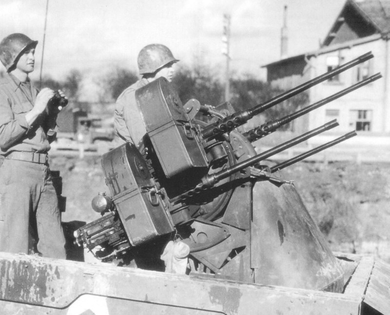
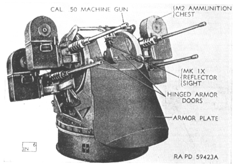
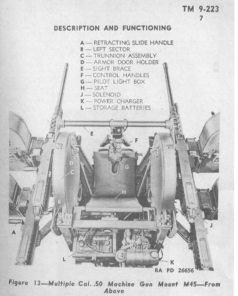
Adding a protective armor shield for the gunner, the new quad .50 was formally known as the Multiple Machine Gun Mount M45 when it went into production in 1943. It armed the M16 halftrack as we know it in the Tamiya kit.
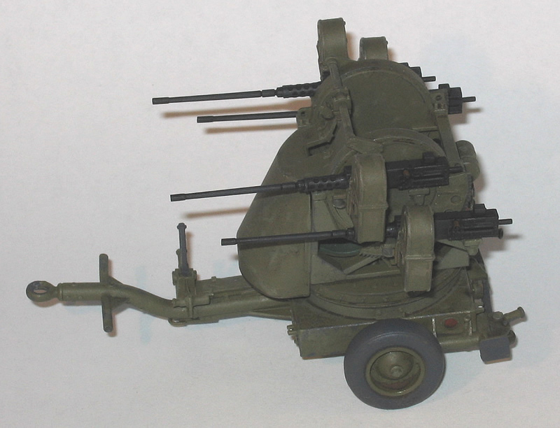
The U.S. airborne asked for a smaller version that could be transported by glider or cargo aircraft. Situated on the Trailer M20 and minus the armored shield, this version was the .50 Multiple Machine Gun Carriage M55. At a little more than 3,000 pounds loaded for combat, it could be pulled by jeep. Firing at a rate of 450 to 575 rounds per minute per gun, this weapon was particularly lethal when applied to ground targets in the field.
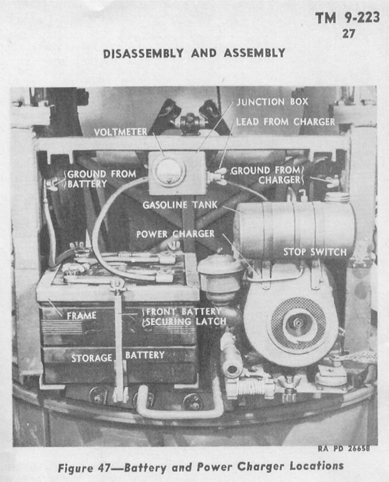
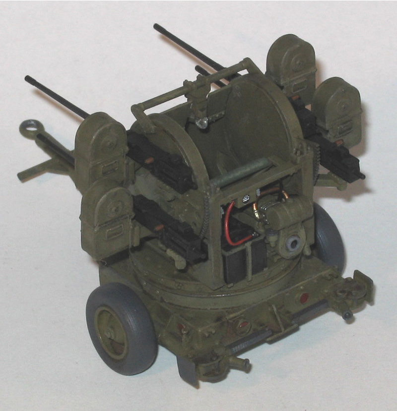
As mentioned, the kit's Maxon mount and guns are molded in styrene. The trailer and ammo cans are resin, and a thin black plastic tube is provided for the tail light's electrical connection. The resin pieces were cast reasonably well: there were sizeable air bubbles on the hub caps of each wheel which needed some repair, but other details were good. There was also a small piece resembling a retaining lock that was missing from one of the cylindrical sleeves on the trailer body. Some putty had to be applied to some slight sink marks on the corner bracing of the side trunnion assemblies.
There are 20 small bolts molded onto one of the styrene sprues, but no indication in the instructions as to what they are for. I did notice in the website photos that there are four bolts on each of the four horizontal corners of the Maxon mount, which are missing on the kit parts. Are the bolts for this use? Nothing else was apparent in the instructions, so I carefully sliced them off and set them in place with some super glue. It's a good thing there were extra bolts, as four of them decided to venture into other realms of my work space. Down to no spares, that last little bolt had a lot riding on him!
In
step seven, the gun mounts are joined with the trunnion via the sight brace; the
kit suggests not gluing the trunnion mounts in place so the guns can swivel up
and down, but I glued them down since I was building the kit for travel mode rather
than emplaced. The sight, part V9, in reality had a clear, angled disc at the
bottom, which reflected the target image for the gunner to see. This is all green
styrene, of course, but I bought a little more realism by carefully drilling out
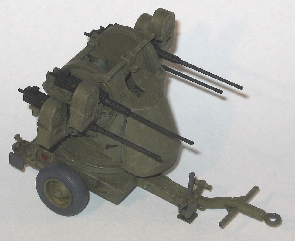
the center of this disk with a pin vise. Note that the instructions in step seven show the two additional bases in place; I think this was just cribbed from the previous guntruck kit's instructions. A little Photoshop work could have cleaned this up. Construction of the Trailer The trailer finally comes into the picture in step eight. While it looks trapezoidal in the M55 image near the top of the page, Hobby Fan's kit portrays the trailer as it was in the WWII era TM 9-233. Construction here is pretty straightforward once you decide if you want to have your quad on the road or deployed for action. In the latter instance, three jackstands attached to the trailer were used to stabilize the gun. Hobby Fan provides two sets of jackstands, retracted and stored for travel, and extended for action. The box photo shows the wheels removed altogether in the deployed mode, which was the common practice described in The American Arsenal.
There are no decals with this kit so you'll need to scrounge up some serial and unit markings from other sources if you desire. Overall I enjoyed building this kit, and it's a good rainy weekend out-of-the-box project. I'm planning on using mine in a towed situation, and Tank WorkShop's .50 Cal Ammo Containers will probably be loaded in the towing vehicle. References The American Arsenal: The World War II Official Standard Ordnance Catalog of Small Arms, Tanks, Armored Cars, Artillery, Antiaircraft Guns, Ammunition, Grenades, Mines, etcetera, introduction by Ian V. Hogg, Greenhill Books, 2001, ISBN 1-85367-470-2. American Tanks of WWII, by Thomas Berndt, Motorbooks International, 1994, ISBN 0-87938-930-3. Maquette Garden, maquettegarden.free.fr/Vehicules/Half-track%20M16/index.xml. Standard Guide to U.S. World War II Tanks & Artillery, by Konrad F. Schreier, Jr., Krause Publications, 1994, ISBN 0-87341-297-4. SVSM Model Club Photo Gallery, svsm.org/gallery/m16. Tanxheaven, www.tanxheaven.com/ljs/halftrackus/halftracksusaljs.htm. U.S. Half-tracks in Combat 1941-1945, by Steven J. Zaloga, Concord Publications, 1999, ISBN 962-361-654-6. Sample kit provided by Hobby Fan. -tss |
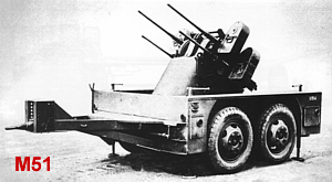 The
Maxon mount next found a home on the large two-axle M17 trailer, which was designated
the .50 Multiple Machine Gun Carriage M51.
The
Maxon mount next found a home on the large two-axle M17 trailer, which was designated
the .50 Multiple Machine Gun Carriage M51. 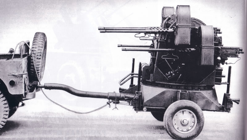
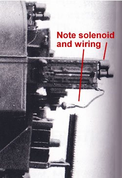 Assembly
begins with gluing a very small butterfly thumb trigger to the rears of each machine
gun. DON'T DO THIS! In all of the photos I found at the aforementioned sites and
others, as well as those in books from Zaloga, Berndt, Schreier, and The American
Arsenal, there was only one contemporary photo of a restored quad .50 that
showed the thumb trigger on the set of MGs. The tech manual and a few period and
contemporary photos of restored quads show a solenoid where the thumb trigger
was found on non-quad .50s. However, guns in many other images, both period and
contemporary, are without solenoids. So, I did not use the butterfly triggers.
Nor did I install solenoids, because I could not get a complete visual understanding
as to how they were wired into the apparatus, but I can add them later. The guns
also lack the barrel changing handles, but those don't appear consistently in
period photos. Be sure to use the tip of a new hobby blade to hollow out the business
ends of the gun barrels. The kit includes flash suppressers, and shows them on
a finished model in the instructions, but I believe this is a post-WWII feature.
Assembly
begins with gluing a very small butterfly thumb trigger to the rears of each machine
gun. DON'T DO THIS! In all of the photos I found at the aforementioned sites and
others, as well as those in books from Zaloga, Berndt, Schreier, and The American
Arsenal, there was only one contemporary photo of a restored quad .50 that
showed the thumb trigger on the set of MGs. The tech manual and a few period and
contemporary photos of restored quads show a solenoid where the thumb trigger
was found on non-quad .50s. However, guns in many other images, both period and
contemporary, are without solenoids. So, I did not use the butterfly triggers.
Nor did I install solenoids, because I could not get a complete visual understanding
as to how they were wired into the apparatus, but I can add them later. The guns
also lack the barrel changing handles, but those don't appear consistently in
period photos. Be sure to use the tip of a new hobby blade to hollow out the business
ends of the gun barrels. The kit includes flash suppressers, and shows them on
a finished model in the instructions, but I believe this is a post-WWII feature.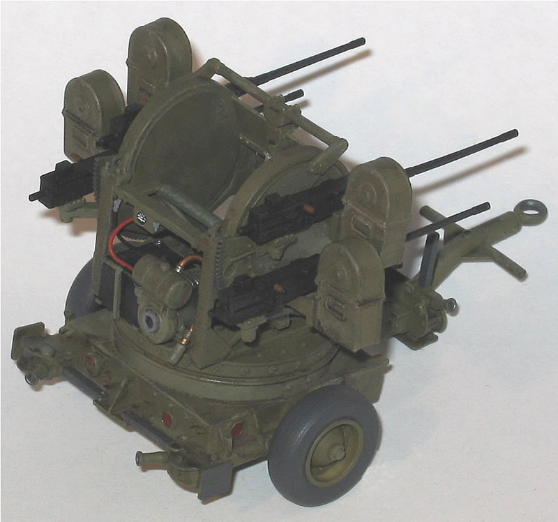
 |
 |
 |
 |
 |
 |
 |
 |
 |
 |
 |
 |
|