|
Building
DML's 105mm Howitzer M2A1 & Carriage M2A1 |
 |
|
Dragon
Models Limited This is a welcome kit of an important weapon in the U.S. arsenal from WWII through the Vietnam War. There were three distinct versions that served during the 1940s, with this M2A1 kit representing the second type. The earlier M2 was virtually identical, but had an electric braking system that was powered by a battery in a small box near the end of the right trail. The M2A1, as seen here, eliminated the electric brakes. The follow-on M2A2 (designated postwar as an M101) is represented by the old Italeri kit, with the most notable changes being the two-part "butterfly" shield that afforded better protection to the crew. (DML's three sprues include numerous parts for an M2A2, which suggest it will handily eclipse the ancient Italeri kit.) It hasn't been exactly impossible to model the M2 or M2A1. Kendall Model Company produced a nice resin and photoetch update set for the Italeri kit in the early 1990s. It included an optional long 3" barrel to alternately build an M5 3" anti-tank gun (though it seems this gun was mounted on the M1 gun carriage only during stateside testing in 1942-43).
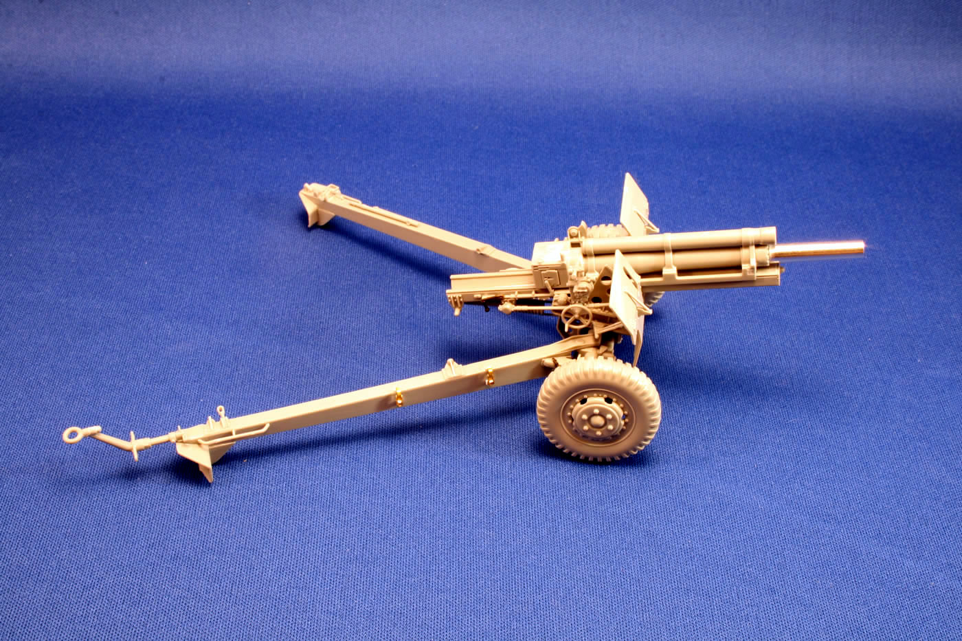
Overall, the parts are very crisp, and many are quite delicate, particularly the small details for the sighting mechanisms and the shield struts. Make sure your hobby knife is sharp and you have a good sanding stick handy. While seams are minimal and pin marks are virtually nonexistent, there are many small pips that are attached to parts to improve the molding and ejection process. The instructions are rather vague at times, and construction will be easier if you access some photos on the web or get hold of the references cited at the end of this article. Keep in mind, though, the different variants as you look at any photos. Construction
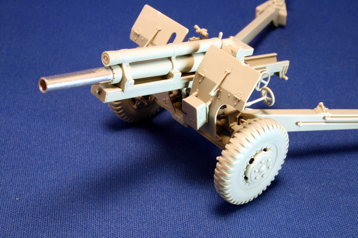
DML would have you glue one half of the elevating arc to one half of the recoil cradle. You would need to match the elevation when assembling the respective pieces for the opposite side-and then you'd be locked into that elevation, particularly since you're also supposed to glue in place the knurled cog that rotated the elevating arcs up and down. From my recent experience building two Italeri and one Academy 105mm assemblies for my Priest projects, I opted to build the long recoil cradle first, then add the two arc pieces and glue them to one another at the elevation I wanted. This enables the gun to pivot up and down, though once you glue the cog in place it engages the teeth of the arcs and you can grind them down with too much movement. You will want to pay attention to the seam along the bottom of the recoil cradle, especially if you are going to have it elevated significantly. I hid the seam in the trough with a thin slice of plastic card.
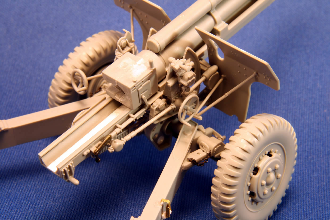
Another quirk: DML nicely detailed a two-piece breechblock, including the small trigger shaft omitted from the Italeri and Academy versions. But as with those versions, you can't realistically portray the breech opened because the main handle on the breech ring is molded in place. I scratchbuilt the parts to open it for my Priest and if you've got a steady hand and sharp eyes you can do it too. But this fairly screams out for a modest aftermarket fix for the breeches of all three manufacturers. The equilibrator spring (part A38) is vastly improved over the parts in Italeri and Academy's 105s. Be sure when you glue the shaft and bracket (parts A8 and A11) for the traversing handwheel to the carriage (B2), you angle the bracket so the handwheel is away from the side of the cradle. That will enable the worm gear at the opposite end of the shaft to engage with the rack (A10).
Here you also are instructed to mount the cradle/recoil unit onto the equalizing support. The instructions do not say "do not cement" and the arrow is grey instead of black. If you don't glue the unit in place, it will fall off, as there is nothing else to hold it to the support. So again, you need to decide sooner than later on a final position for the parts. Make sure you get the aluminum tube positioned properly in the housing. There is some play and you could end up with an off-kilter barrel if you're not careful.
The instructions call for installing the M12A2 panoramic telescope in the M21 telescope mount (part A21) to the brackets (A19 and A20) at this point. I'll wait until just before painting so I don't damage these delicate parts while the build continues. Make sure you glue A21 in a position perpendular to the ground, and not angled with the raised howitzer.
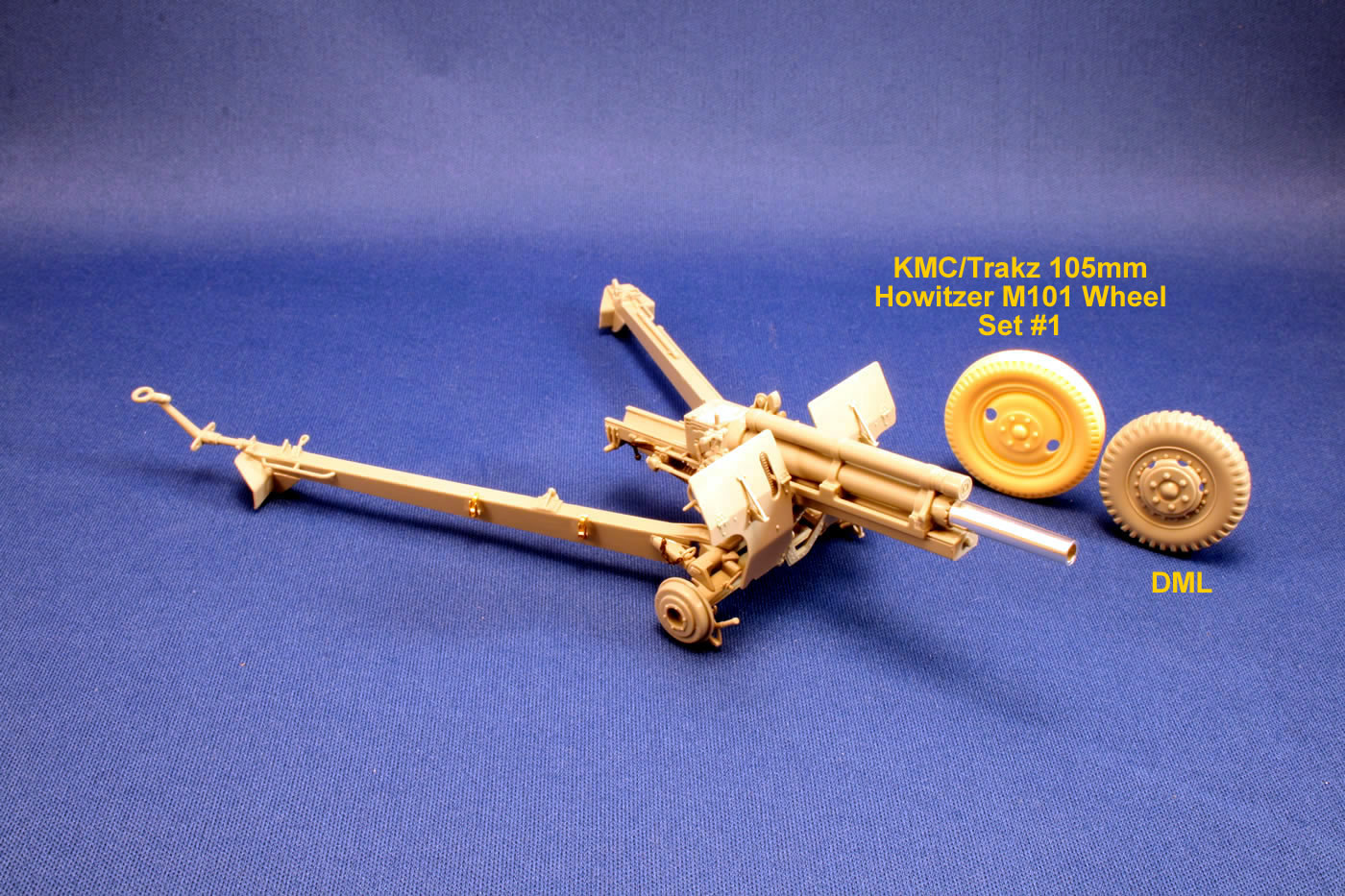
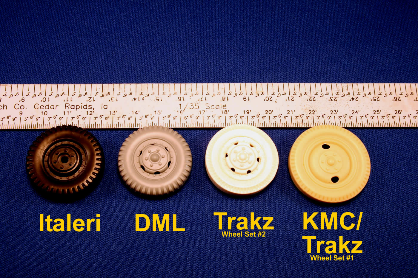
The diameter of the DML tires is about 38 inches. But according to measurements provided by Kurt Laughlin, the mud and snow tires should be 40.1 to 40.5, and the commercial highway tire was measured at 40.39 inches. Unfortunately, the actual measurements fall in between the tires available, as seen below. The Italeri, DML, (both mud and snow) and theTraxz 105mm Howitzer M101 Wheel Set #2 (a highway tire)—as well as a tire produced by Masters Productions (another highway tire, 38.7 inches)—are short. The larger Trakz 105mm Howitzer M101 Wheel Set #1, a repop of the highway tires in Kendall Model Company's upgrade sets, scales to 42.3 inch tire on a large dished rim; alas, it is too large. The Italeri, DML, and Trakz 2 tires are mounted on divided combat wheels, the Trakz 1/KMC wheels are commercial types.
The instructions show the hand brakes positioned more toward 12 o'clock, but when constructed they jut out at 10 o'clock/2 o'clock angles. I'm not sure if that suggests they are engaged or not.
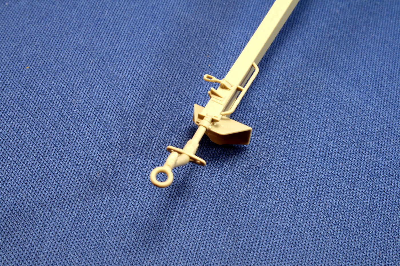
The aiming stakes (C22) are bundled solid with their securing latches, with some thick pad underneath. I'm not sure what that is (a canvas case?) but it doesn't represent anything that is permanently attached to the right trail. Because my howitzer will be deployed in battery, the posts are removed and set out away from the gun for aiming. That helpfully eliminates trying to candy stripe them red and white! If modeling in the firing position, you can carefully drill out the loop in the traveling lock connection pin (C14). The handle (C4) sits raised above the surface of the trail a tad. You won't need much more than olive drab and dark grey to paint the metal parts and rubber tires, though the instructions suggest an optional winter camo whitewash. Careful weathering will help bring out the many details. The CrewDML repurposed its set of 101st Airborne winter figures for this kit, including three new arms to better adapt the soldiers for carrying ammo and working the gun. There have been valid complaints that cannoneers did not wear web suspenders and cartridge pouches as a matter of course-especially BAR pouches! The first simple fix is to not add the pouches. Crew men were usually equipped with M1 carbines, so you could add an appropriate pouch if you have some spares on hand and your boys might be close enough to the enemy to need their sidearms quickly. The next fix is to carve off the suspenders and use a bit of putty to fill the coats as necessary. A little time-consuming perhaps, but the most economical approach. Or, you can avail yourself of several decent resin figure sets from Warriors, Verlinden, Resination, and Dynasty (the latter two may be out of production and more difficult to find). The 105mm howitzer was crewed by nine soldiers, and pulled by a 2.5 ton 6x6 truck, which is offered by Tamiya (softtop) and Italeri (soft and hardtop). There also is a multitude of aftermarket ammo sets and accessories that will help you extend a relatively trouble-free, reasonably priced artillery kit into a full blown diorama. ConclusionWhile this is not a perfect offering, it is much more refined that Italeri's kit (which still is not that bad) and looks very nice when completed. We'll have to wait for the aftermarket boys to give us some accurately sized tires—and a breech ring with an open lever would be a nice option—and a proper set of aiming stakes. In the meantime, this article can help you get through some of the bumps that DML should have worked out (my invoice is in the mail to Mr. Takada and the H3 Design Office). This kit was followed in February 2011 by the 105mm Howitzer M2A1 and Carriage M2A2 w/USMC Crew. Build and enjoy! ReferencesSee the 105mm M2A1 on the M2A2 carriage at the Victory Museum in Auburn, Indiana. Also on the page are tech manual images that will help with the details. FM 6-75 105-mm Howitzer, M2, Truck-drawn, War Department Field Artillery Field Manual, December 12, 1941. TM 9-1325 105-mm Howitzers and M2 and M2A1; Carriages M2A1 and M2A2; and Combat Vehicle Mounts M3 and M4, Ordnance Maintenance, War Department Technical Manual, 21 September 1944. Standard Guide to U.S. World War II Tanks & Artillery, by Konrad F. Schreier, Jr., Krause Publications. U.S.
WWII 105mm Howitzer Motor Carriages M7 & M7B1 Priest, Michael Franz,
editor, Tankograd Publishing. -tss- |


 |
 |
 |
 |
 |
 |
 |
 |
 |
 |
 |
 |
|