| LVT-4 Late Type Water Buffalo |
 |
|
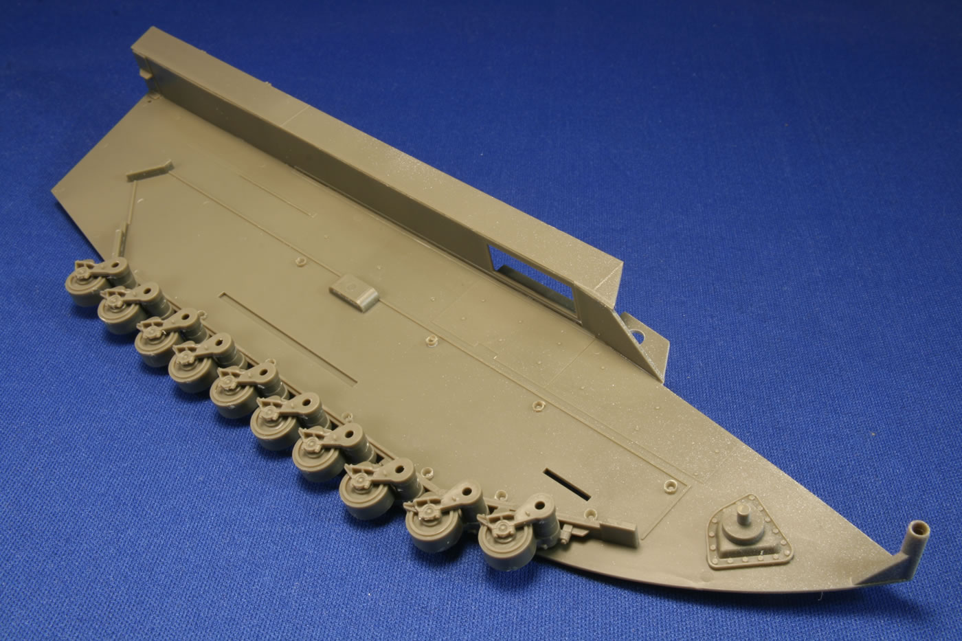
AFV Club As with nearly all of the land-based armor during WWII, there was an evolution in amphibious armor. The various “alligators” and “buffalos” developed by the US varied mostly in armament, engine/cargo placement, and egress of ferried soldiers. The LVT-4 moved the engine forward to behind the driver’s compartment and provided a rear ramp that enabled soldiers and cargo to disembark more easily (and more safely for the soldiers, who previously had to jump over the sides of other variants). The late LVT-4 differed from the earlier version in the addition of side and bow armor plates, some of the fittings on the body of the beast, and removing the Plexiglas dome over driver’s periscope. Over time, the forward .50 machine gunners increased their protection from a single armored plate, to a curved plate that provided more coverage, to a box-like structure that gave overhead cover as well. While I have not seen its early version of the LVT-4, AFV Club has done a fine job providing the requisite updates for this vehicle, when referenced against Toadman's LVT(4) Walkaround CD. There are a lot of small, fragile parts in this kit, so I wouldn’t recommend it for youngsters or less confident modelers. A fresh blade in the Xacto is a must, and the trusty nippers are extremely helpful in removing parts from the trees. Some of the connection points are thicker than the pieces, and in numerous instances it is easier to gently remove burrs from thin parts after they have been securely glued to the model. This is not a kit to build in a rush. It often helps to wait for the glue to dry solid before continuing on with certain assembled parts, such as the wheel assemblies. Assembling the PontonsThat’s right: pontons, not pontoons. These are the large structures along the sides of the cargo hull wherein fuel was stored. The instructions begin with this assembly process, and be forewarned, there are a lot of wheels, and a lot of little parts. But once you get into the groove it moves along pretty well. There are no mold seams to deal with, but you want to make sure you eliminate any burrs, so some clean-up is necessary. At Step 3, you are asked to choose the option to add the side armor to the pontons. Actually, you can add this at the very end if you’d like, which might make sense as there are little tabs across the armor plates that are easy to break off (I had to replace a couple with scrap plastic). Some of the parts in this section, such as C2 and C3 have slightly raised circles on them that should be removed with your knife or sanding stick. Steps 5 through 9 take you through the hull wall assemblies, both exterior and interior features. It’s good to take your time and dry fit the parts to make sure you have them lined up properly. There are a lot of right angles involved and it would be helpful if there were exploded views to see where plates matched up. It helps to look forward a step or two to see where subsequent pieces come into play. For example, the rear cargo door cable is added in Step 7 and then covered with parts so as to be inaccessible. I wrapped the provided thread around a piece of scrap plastic and glued that securely inside the bin so there would be no way it would come undone. (Naturally, if you want your ramp closed, you don’t need to deal with the thread.) There’s a small fret of photoetch included in the kit, and the first two pieces come into play at this point: the mesh screens for the air exchange vents in the side sponsons. After you get the two sides assembled, it’s good to paint the interior driver’s cabin white. The instructions call for adding the fire extinguisher at this point, but I held off until the model was complete, painting it red and adding a spare decal from Fingerprint Designs (this should have been included in the kit’s decals).
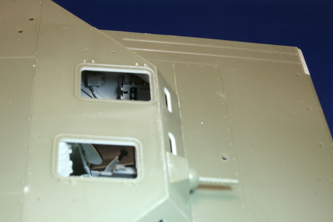
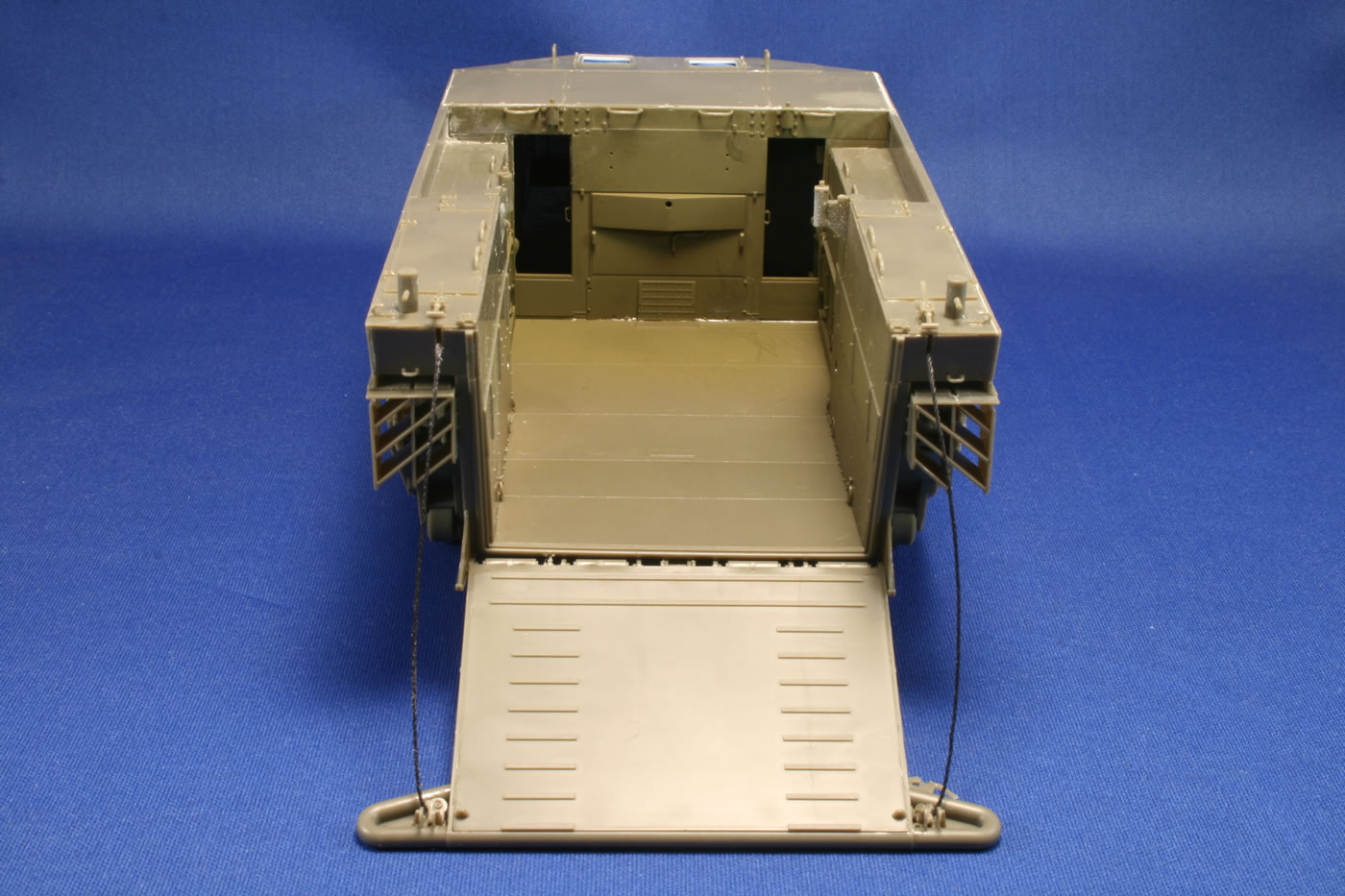
Step 12 suggests adding the front drive sprockets, but I waited until I was ready to loop the track around the suspension. The Driver’s CompartmentSteps 13 through 18 bring the crew cabin together. It’s an impressively detailed interior that no one will see if the crew hatches are closed, and little is evident if they are left open. But it was fun to build, paint, and weather. I even added the electrical conduit and cabling just to know “it’s there.”
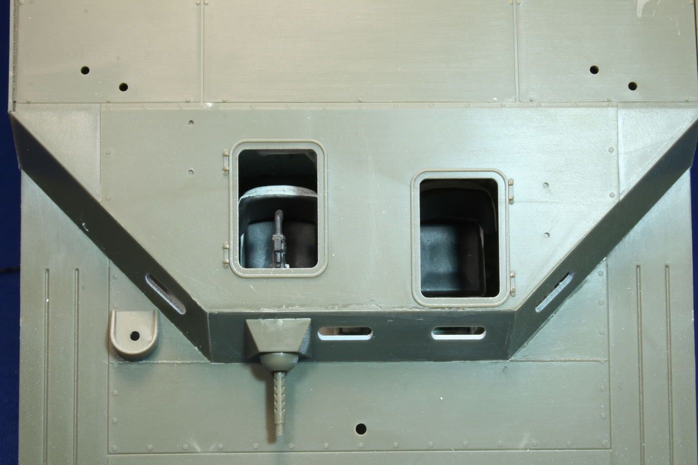
You finally get a real sense of how big this kit is as you put together the hull floor in Step 18 and join it with the cabin assembly and bulkhead. Not often you work with big flat pieces of plastic like these in armor modeling! However, one curious omission here is the lack of photoetch screens for the drain openings. The kit includes a clear part for the small square “dashboard” and film printed with gauges, but you can’t read the gauges through the clear plastic and the whole thing is pretty much obscured from view. But again, nice to know it’s in there. Now we come to the point in the build where I may have outfoxed myself. In Step 19, the hull/ponton units are attached to the center floor unit. Looking ahead, I saw that the engine walls behind the crew would be installed. This area is covered and I figured it would be difficult to paint. So—departing from the instructions—I put together the three parts of the engine walls (C4, C5, and E15), added a couple screens of photoetch, and sprayed this and the inner sides of the cargo compartment OD.
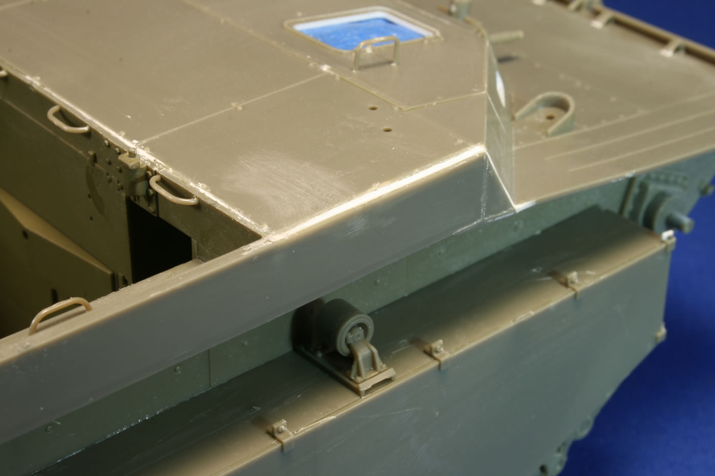
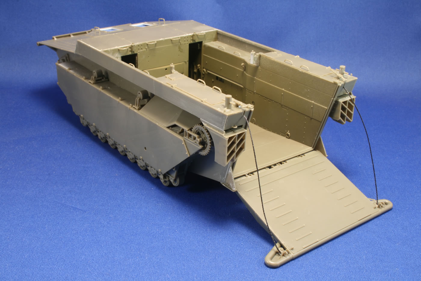
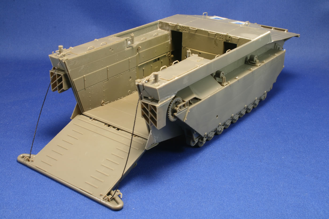
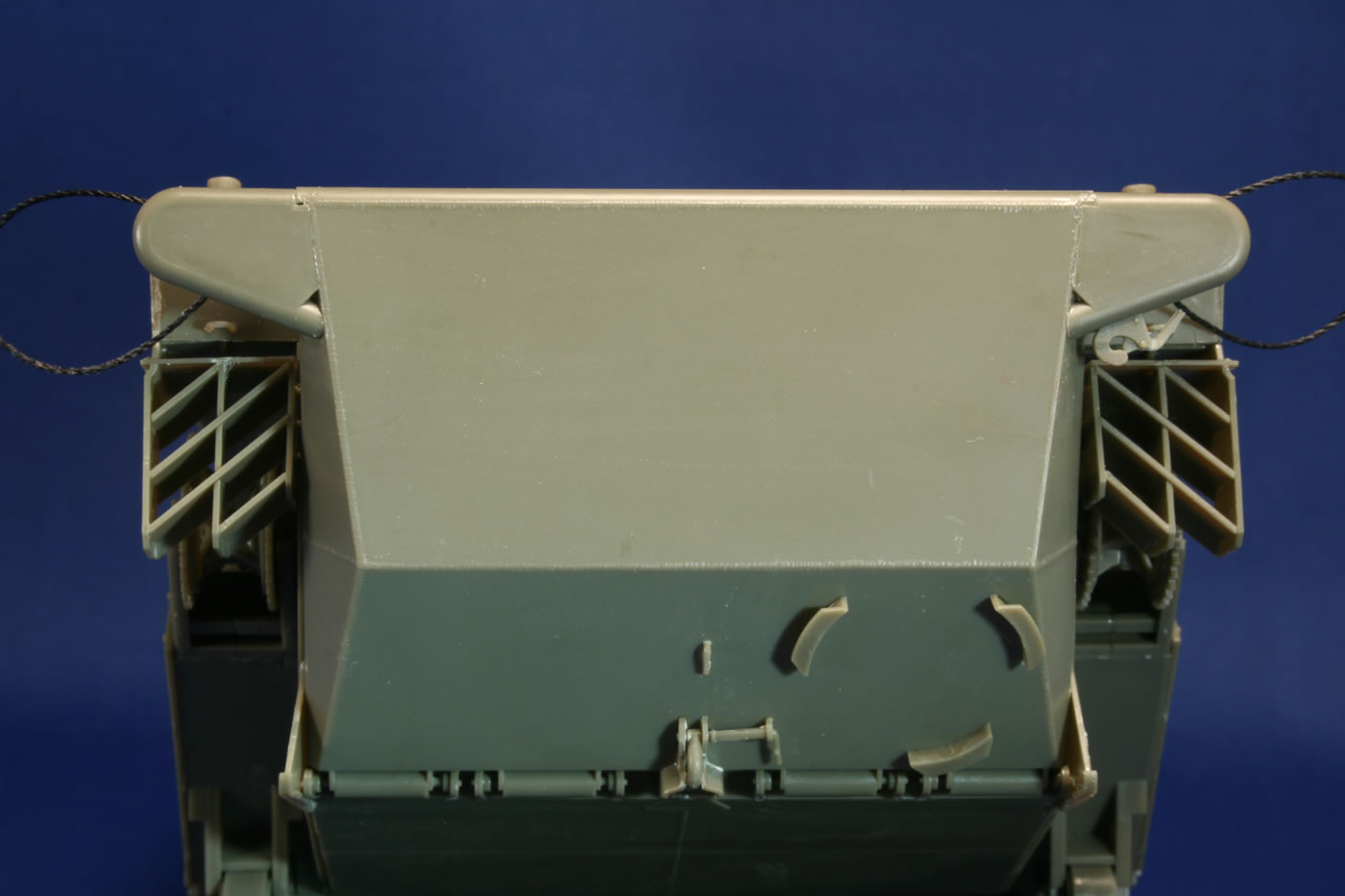
There are a number of parts to add to the cabin roof before topping off the crew compartment. The glass blocks were withheld until after the finishing was finished, so as not to get anything on the clear parts, and hand painted the armor surrounds. Likewise with the hatches and clear periscope, and the long poles. The .30 cal machine gun and fittings were glued in place. The RampThe rear ramp is the focus of steps 25 through 29. You need to drill holes on either side of the ramp to snake the cable thread through. To the thread you attach the pulley parts, which nestle into large elbows glued at the top corners of the ramp along with some latch pieces. BUT, I waited to put the pulley parts to these elbow until after I glued the ramp to the hull floor because it’s important to get the tension of the thread right and I knew it would be tricky once the pulleys were glued down since it’s hard to pull the thread back and forth through them. So, after running the thread through the ramp (part E1) and gluing the floor plate (part E5) to E1, I began to add the numerous K15 parts to the bottom of the hull and let them dry. This way, I had something solid to work with when setting the ramp bottom in place and trapping the hinge pintles with the parts K16. After these dried, I had a moveable ramp. While this was setting up, I moved on to Steps 30 and 31, which are the vane assemblies near the rear idlers. These were criticized as rather thick in the Italeri kit, but they are acceptably thin in AFV Club’s model, and beat the hell out of trying to glue or solder photoetch parts. But be sure they are squared off properly so you don’t have problems attaching them to the hull walls. Now, back to the ramp…. If everything is dry and secure, and you haven’t gotten glue on your small pulley parts, you should be in good shape to attach the other end of the cable thread. At this time, slip the assembled tracks over the ponton assemblies so have the right height for the extended ramp. Things to keep in mind: will the model be used in a diorama, where it would likely be sunk into beach sand, or will it be displayed on a piece of wood, where the height from the ground will be similar to your work surface? By carefully pulling on the thread through the little pulleys, you can get the desired tension for the left side of the ramp cable (looking forward). The trick now is to get the right side length correct so there isn’t any slack in the left side because it is too tight. After slipping the thread through the back of the bin on right side of the hull (looking forward), I cut a notch into the center support inside the bin. I tied the thread to a piece of plastic and wound it until I got the right side of the cable as taut as the left side. I set the thread into the notch, with the piece of plastic on the other side, and after making sure things were pretty much as I wanted them to be, I gave the tied plastic a glue bath. This baby wasn’t going to go anywhere. After it dried, I cut off the remaining thread and glued the lid parts in place. I ran some thinned glue over the threads and put some weight on the ramp to keep them taut while they dried. This gave them some added stiffness. At this point you can decide whether to glue the ramp in place or wait until you’re sure of what it will be sitting on. Final Bits
The machine guns are very nice reproductions. The .50 cal. guns come drilled out at the muzzles, but the .30 cal. are not. I also drilled out the solid sight over the .50s’ receivers with my knife tip. I left the lids off of the .50 cal. ammo boxes and thinned the edges to trick them out later with some ammo rounds fed into the receiver. With three different types of shield and no guidance on which to use for the late LVT-4, I went with the later “box” version to be safe. There are some pin marks on the back sides of the plates that should be filled. AFV Club’s partner Hobby Fan makes a pair of machine gunners that I hope to get my hands on so I can give the guns a little action. I mentioned the track earlier, and should point out that each length is made of two parts that can glue together with model cement. It’s a bit different from your typical track in that there are linkages that must be engaged when assembled. The rubber is thin and flexible. I used some dark brown Krylon plastic paint on the tracks and it took well with no flaking. Finally, there is a place to secure towing cable on the rear of the ramp, and the towing eyes are included in the kit, but there is no indication in the directions to assemble them, or whether the remaining length of thread should be used for that purpose. I’m not sure of the actual length but I used the thread and plastic parts so I would have something to wrap around the stowage fixture—which, when all is said and done, won’t be very visible beneath the extended ramp.
Painting and DecalsThe kit comes with paint call outs and decals for four vehicles. Only two of these are U.S. WWII, however. One is solid OD as used at Okinawa, and the other is described as “U.S. Marine, Americans in Wartime Museum, 2009.” This is a three-color paint job and as green is called for instead of OD, it may not even be WWII. I wasn’t able to find any additional info on this scheme but I didn’t delve into it too deeply. The AFV Club decals are VERY thin and may not tolerate a lot of jiggling around before folding over on themselves, so slide them with wet brush. I used Fingerprint Designs for the "Lift Here" markings. ConclusionSo what is missing from this kit? Nothing aside from some decals and the crank handle for the ramp would be typically seen in a diorama setting. Most of us have an ample supply of MG ammo boxes handy (though not in the particular style used here) and other crates and stowage to fill the hold if not occupied by beach invaders. Some clarity on the museum paint job and the appropriateness of any of the three .50 caliber machine gun armor versions with this late variant would have been reassuring. Likewise, painting and decal illustrations show the ponton sides without the extra armor plates, likely a holdover from the instructions for the earlier version of the kit. Then again, the nicely rendered box art for the late version shows no side armor and uses intermediate shields on the big machine guns. There have been a couple complaints online about lack of an engine, but this would be completely obscured by the walls and only seen if one were to do a maintenance diorama. It would be an extra cost borne by all to satisfy a very small few, so the aftermarket wizards will have something to contribute. As it is, the pretty complete interior for the crew compartment will not see the light of day in many instances. Again, this is not a weekend build, but you’re not going to have to invest a lot of time researching missing details. I'd have to say this is one of the most complete and accurate kits I’ve built. Check back soon for photos of the painted model. Review sample provided by AFV Club. -tss |


 |
 |
 |
 |
 |
 |
 |
 |
 |
 |
 |
 |
|